The Submerged Arc Furnace (SAF) Process
The submerged arc furnace process involves the intermittent charging of raw materials into the furnace via a feeding system. A stoking machine maintains the material bed level. Molten alloy is tapped, flowing into ladles or other containers, and is then transported to molds for casting. The final product is formed after cooling. Iron slag is intermittently discharged through a dedicated slag tap hole.
Main Equipment of the
Submerged Arc FurnaceThe SAF system primarily consists of the following components:
* Furnace Body & Lining
* Furnace Cover
* Short Network
* Water-Cooling System
* Exhaust Gas & Dedusting System
* Waste Heat Treatment System
* Electrode Shell
* Electrode Holding, Slipping, and Lifting System
* Charging & Discharging System
* Control System
* Burn-Through Device
* Hydraulic System
* SAF Transformer and Associated Electrical Equipment
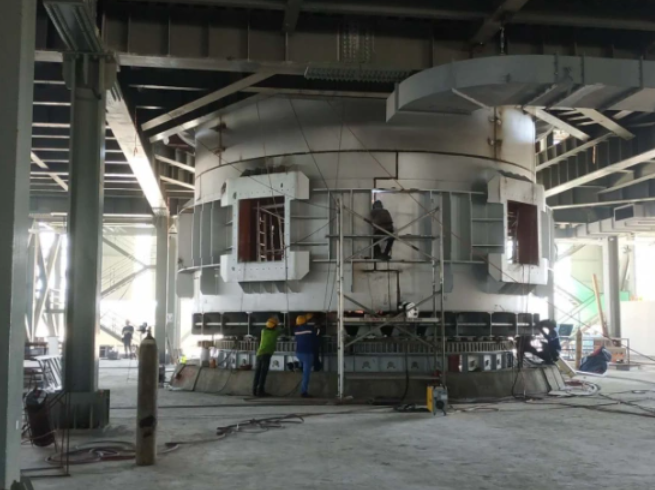
Furnace Body
The furnace body comprises a steel shell and a refractory lining.
* Furnace Shell: Constructed from a bottom plate, side plates, reinforcing hoops, and rib plates. It typically features a circular design with thick steel side plates supported by a channel steel framework anchored in concrete.
* Lining: Utilizes high-alumina, magnesia, and carbon-based refractories. First-grade magnesia bricks and materials are employed near the tap-hole, often combined with other refractories like carbonaceous silica bricks.
* Shell Requirements: Must possess sufficient strength to withstand severe thermal expansion of the lining, accommodate heating and cooling cycles, and be material-efficient and manufacturable. The shell incorporates an integrated tap-hole.
Furnace Cover
The cover on sealed furnaces is constructed with refractory bricks and materials, using water-cooled steel beams as its skeleton. It features three electrode ports for the electrode holders, insulated from the cover. Temperature measurement sockets with protective tubes are installed in the refractory brickwork to monitor furnace atmosphere temperature under the cover.
Fume Hood
The hood seals the furnace mouth, contains radiant heat, and captures flue gases generated during smelting, improving the working environment. It is a welded steel structure (often hexagonal) consisting of cover plates, side walls, doors, and a supporting skeleton that sits on the operating platform.
Flue Gas Outlet Pipe
This system creates negative pressure within the hood (via natural draft or a fan) to extract smoke. Each furnace typically has two flues, constructed from steel plates and profiles. A flue assembly includes a lower water-cooled section seated on the hood, a connecting pipe section leading outside, and a bell valve (operated by a hydraulic cylinder) to open/close the flue. When closed, gases are directed to the dedusting system.
Electrode Holder
This is a core SAF component, comprising:
* Conductive Device: Traditionally includes collector rings (for current distribution and equalization), conductive copper pipes, and copper tiles (water-cooled, red copper castings). Copper tiles transmit current to the electrode.
* Holding Device: Applies pressure via copper tiles to the electrode shell.
* Slipping & Lifting Devices: For electrode length adjustment and positioning.
* Holding Cylinder: Also called the electrode outer cylinder, it suspends the holder and electrode, allowing for vertical movement.
* Electrode Shell: Contains the electrode paste, which sinters to form the consumable electrode.
The copper tile-to-electrode contact pressure is typically 0.05–0.15 MPa. The electrode sintering zone is a critical area for strength.
Electrode Lifting Device
This adjusts the electrode arc length to control circuit resistance and current. Lifting speed varies with furnace power and electrode diameter (e.g., 0.2–0.5 m/min for diameters >1m). The typical lifting stroke is 2.1–2.6 meters.
Short Network System
The short network transmits low-voltage, high-current power from the transformer to the electrodes. Its design is crucial for electrical efficiency and minimizing non-ferrous metal consumption. Key requirements are:
1. Adequate current-carrying capacity.
2. Minimized resistance.
3. Low inductive reactance.
4. Sufficient insulation and mechanical strength.
Short Network Compensation
The short network contributes approximately 70% of the system's reactance, resulting in a low natural power factor (often 0.7–0.8). This reduces transformer efficiency, wastes energy, and may incur utility penalties. Implementing compensation (power factor correction and phase balancing) is an effective means to lower energy consumption and improve smelting efficiency.
High-Voltage Power Supply System
This system includes high-voltage isolators, voltage/current transformers, vacuum circuit breakers, zinc oxide arresters (for lightning protection), and RC snubbers (for overvoltage protection). It supplies main power to the furnace transformer and provides short-circuit and overvoltage protection for the primary circuit.
Cooling Water System
Water is supplied to a high-level platform and distributed to cool various components: the short network, fume hood, chimney, pressure rings, copper tiles, and large water jackets. A separate stream cools the transformer via a forced-oil/water heat exchanger.
Key Spare Parts
1. Furnace refractory materials.
2. Electrode paste.
3. Transformer rails and fasteners.
4. Hydraulic fluid.
5. Copper tiles.
6. Water-cooled cables.
The above provides an overview of the submerged arc furnace process and its main equipment. For more specialized information on smelting furnace technology, please refer to the updates on our website.
For further inquiries, or if you require submerged arc furnaces, electric arc furnaces, ladle refining furnaces, or other melting equipment, please do not hesitate to contact us at susan@aeaxa.com.


